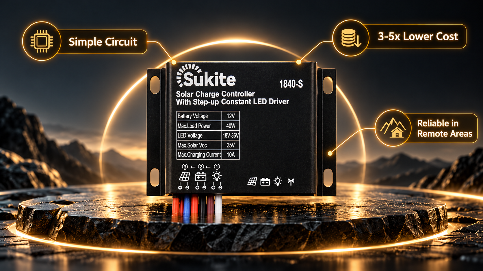


In solar lighting systems, there’s a seemingly simple yet often confusing problem: battery voltage is often “not enough.”
A 12V battery reads about 14.4V at full charge and about 10.8V at under-voltage protection. But an LED street light string may need 18V, 24V, or even 36V to operate properly. Connect a 12V battery directly to an LED string requiring 36V, and the light simply won‘t turn on — the voltage is too low for the LED’s PN junction to conduct.
The solution to this contradiction lies in the boost circuit inside the controller. The core task of a boost controller is to raise a lower input voltage to a higher output voltage — enabling the battery‘s “low voltage” to drive the load’s “high demand.”
To understand a boost controller, you first need to understand a basic circuit principle: an inductor “resists changes in current.”
When current flows through an inductor, the inductor converts electrical energy into magnetic field energy and stores it. When the current tries to stop, the inductor generates a reverse voltage attempting to maintain current continuity. Boost circuits exploit this characteristic.
The core circuit of a boost controller consists of four key components: an inductor, a switch (usually a MOSFET), a diode, and a capacitor. Its operation has two phases:
Phase 1: Switch on, inductor stores energy. When the switch is on, input voltage is applied across the inductor, current begins to flow, and the inductor converts electrical energy into magnetic field energy. At this point, the diode is reverse-biased, and the capacitor independently supplies the load.
Phase 2: Switch off, inductor releases energy. When the switch turns off, the inductor’s current tries to continue flowing, and the inductor generates a reverse voltage. This reverse voltage stacks on top of the input voltage and, through the diode, supplies the capacitor and load. The result: output voltage equals input voltage plus the voltage generated by the inductor — this is the essence of “boosting.”
By adjusting the switch‘s “duty cycle” (ratio of on-time to total period), the output voltage can be precisely controlled. The larger the duty cycle, the more energy the inductor stores, and the higher the output voltage. In actual circuits, the controller monitors output voltage in real time through a feedback loop and dynamically adjusts the duty cycle to keep output voltage stable at the set value.
The most common application of boost controllers in solar lighting is driving high-voltage LED strings.
In traditional solar street light systems, if the LED string’s operating voltage is higher than the battery voltage, a separate LED driver power supply is typically required. This driver boosts the battery voltage to the LED string‘s required operating voltage and drives the LEDs with constant current. The controller and LED driver are two separate devices, each with its own housing, terminals, and thermal design.
Controllers with built-in boost constant current drivers combine these two devices into one. While performing charge management, the controller directly outputs boosted constant current at the load terminal to drive the LED string. This integrated design reduces device count, simplifies wiring structure, minimizes failure points, and saves installation space and overall costs.
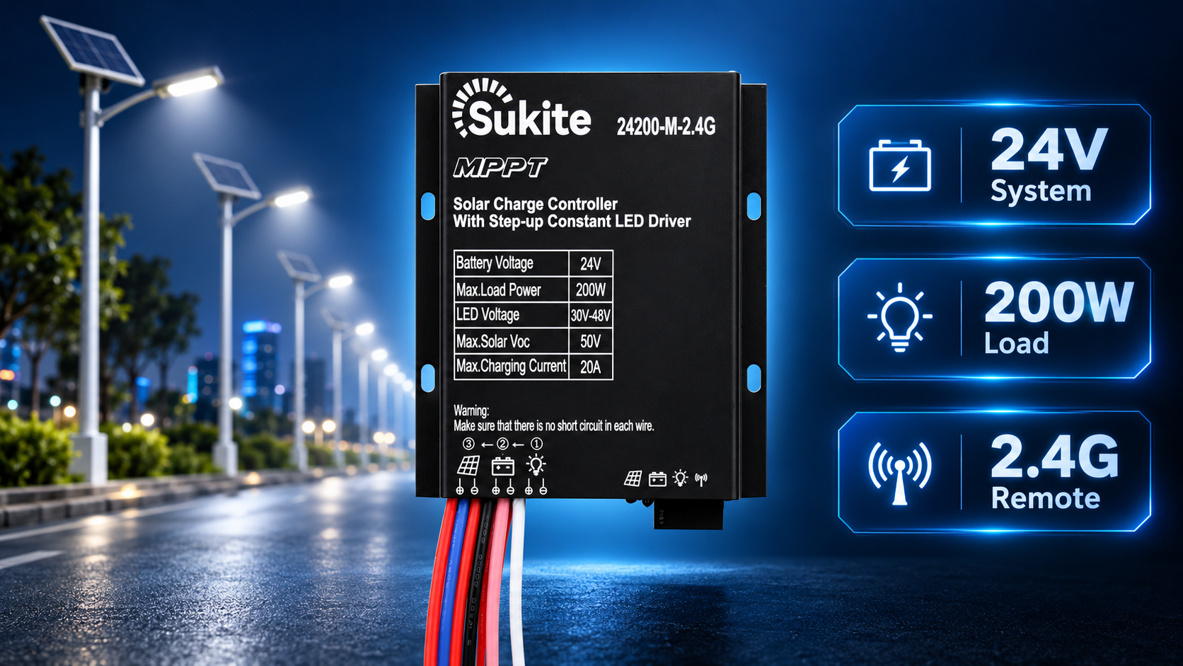
Take Sukite’s 3229-G as an example. It supports 3.2V LiFePO₄ battery systems with an LED output voltage range of 9V-36V. This means it can boost the 3.2V battery voltage to any set value between 9V and 36V, driving the LED string with constant current. The 3240-G raises the charging current to 20A and load power to 40W, further expanding application boundaries. The 2480-M supports 24V battery systems with an LED output voltage range of 30V-48V, suitable for medium-power off-grid lighting scenarios.
Boost controllers and buck controllers are two opposite DC-DC conversion topologies. Understanding their difference is key to selecting the right controller.
Buck controllers step down a higher input voltage to a lower output voltage. Their typical application: solar panel voltage higher than battery voltage. For example, an 18V solar panel charging a 12V battery — if connected directly, the 18V would continuously stress the 12V battery, causing overcharging, heating, or even damage. A buck controller steps down the 18V to a voltage suitable for 12V battery charging (approximately 13.8V-14.4V) while charging with constant current.
Boost controllers step up a lower input voltage to a higher output voltage. Their typical application: battery voltage lower than the load‘s required operating voltage. For example, a 3.2V LiFePO₄ battery powering an LED string that requires 9V-36V — the boost controller steps up the 3.2V to the LED string’s required voltage range and drives the LED with constant current.
The fundamental difference: a buck controller‘s input voltage must always be higher than its output voltage; a boost controller’s input voltage must always be lower than its output voltage. If the input-output relationship is not fixed, a buck-boost controller is needed, which can automatically step up or step down as required.
When selecting a boost controller, the following key specifications should be considered:
Input voltage range: The input voltage range within which the controller operates normally. For solar lighting applications, input voltage typically comes from the battery and must cover the full range from full charge voltage to under-voltage protection voltage.
Output voltage range: The voltage range the controller can output. This range must cover the LED string‘s required operating voltage. For example, if the LED string requires 36V, the controller’s output voltage range must include 36V.
Maximum output current: The maximum current the controller can continuously output. This specification determines the maximum power of the LED string the controller can drive.
Conversion efficiency: Boost circuit conversion efficiency typically ranges from 85% to 95%. Higher efficiency means lower energy loss and longer battery runtime. High-efficiency boost controllers typically employ synchronous rectification and low on-resistance MOSFETs.
Constant current accuracy: For LED driving applications, output current accuracy directly affects LED brightness and lifespan. High-precision constant current control can limit current fluctuation to within ±3%, ensuring LED chips receive stable driving current.
Early boost controllers used analog circuits, controlling the switch duty cycle through operational amplifiers and comparators. This approach was simple and low-cost but limited in precision and flexibility, making complex protection functions and communication capabilities difficult.
Modern boost controllers increasingly adopt digital control technology. Through a microcontroller (MCU) sampling input voltage, output voltage, and output current in real time, control algorithms dynamically adjust switching frequency and duty cycle, achieving more precise constant current control and richer protection functions. Digital control also enables programmable output voltage, remote monitoring, and firmware upgrades.
At the power device level, wide-bandgap semiconductors (such as silicon carbide SiC and gallium nitride GaN) are gradually replacing traditional silicon-based MOSFETs. Wide-bandgap devices offer higher switching frequencies, lower conduction losses, and higher operating temperature tolerance — enabling boost controllers to be smaller, more efficient, and more reliable.
A boost controller is essentially a “voltage amplifier.” Its core purpose is to solve the problem of raising voltage when battery voltage is insufficient to drive the load. For LED lighting systems, boost controllers enable low-voltage batteries to drive high-voltage LED strings, ensuring every LED chip receives stable driving current. Choose the right boost controller, and the light will shine steadily and last.
Fill out the form below and our team will get back to you within 24 hours.
Your inquiry has been submitted successfully. Our team will contact you within 24 hours.